What is an electrical schematic diagram:What is an electrical schematic diagram?
Q: What is an electrical schematic diagram?
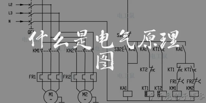
A: An electrical schematic diagram, often called a circuit diagram, is a graphical representation of an electrical circuit. It uses standardized symbols to depict components such as resistors, capacitors, inductors, diodes, transistors, and integrated circuits, as well as the connections between them. Unlike pictorial diagrams that show physical appearance, schematics focus on electrical function and connectivity. Lines represent conductive wires, while symbols indicate the type and value of each component. Schematics are essential for designing, analyzing, troubleshooting, and documenting electrical and electronic systems. They allow engineers and technicians to understand how a circuit works without needing to see the physical layout. Because they are abstract, schematics can represent complex systems in a clear, concise manner, making them a universal language in electronics.
Q: Why are schematic diagrams important for troubleshooting electrical circuits?
A: Schematic diagrams are crucial for troubleshooting because they show the logical flow of signals and power through a circuit. By comparing measured voltages or signals at various points with expected values, a technician can isolate faults quickly. The diagram reveals how components interact, so if one part fails, you can trace the effect through the circuit. Without a schematic, troubleshooting becomes guesswork, especially in complex systems with hundreds of connections. Schematics also help identify test points and understand the purpose of each wire. They allow you to verify that the physical wiring matches the intended design, catching errors or modifications. In addition, they are indispensable for reverse-engineering unknown circuits or repairing damaged boards where labels are missing. Overall, a schematic turns a confusing tangle of wires into a clear map for systematic diagnosis and repair.
Q: What are the key symbols used in electrical schematic diagrams?
A: Electrical schematics use a standard set of symbols defined by organizations like IEEE and IEC. Common symbols include: a zigzag line for a resistor, two parallel lines for a capacitor, a coil for an inductor, a triangle with a line for a diode, and a circle with a triangle for a transistor. A circle with a plus and minus represents a DC voltage source, while a wavy line indicates AC. Switches are shown as a break in a line with a hinged arm, and ground is a series of decreasing horizontal lines. Connectors are often depicted as open circles or pins. Logic gates like AND, OR, and NOT have distinctive shapes. Understanding these symbols is essential to read or draw schematics. Since symbols are standardized, an engineer anywhere can interpret a circuit correctly, promoting clear communication and reducing errors in design and documentation.
Q: How does an electrical schematic diagram differ from a wiring diagram or layout diagram?
A: An electrical schematic diagram focuses on electrical connectivity and function, not physical location. It uses abstract symbols and ignores the actual placement of components or wire lengths. In contrast, a wiring diagram shows the physical connections between components, often including terminal numbers, wire colors, and routing paths. It is more pictorial and helps with actual assembly. A layout diagram, also called a physical layout or PCB layout, shows the exact positions of components on a board or panel, including traces and dimensions. While schematics answer 'how does it work electrically,' wiring and layout diagrams answer 'how is it built physically.' All three are complementary: a schematic is used for design and analysis, a wiring diagram for installation and repair, and a layout for manufacturing. Confusing them can lead to errors, so it's important to know which type you need for a given task.
Dialogue about
Common scenarios of "What is an electrical schematic diagram"
【Learner】 Hi, I've been hearing the term 'electrical schematic diagram' a lot. Can you tell me what it actually is?
【Instructor】 Sure! An electrical schematic diagram is a drawing that uses standardized symbols to represent electrical components and their connections. It shows how a circuit is wired logically, not necessarily physically.
【Learner】 So it's different from a wiring diagram or a physical layout?
【Instructor】 Exactly. A wiring diagram shows the physical placement and actual wires, while a schematic focuses on the electrical relationships. It's like a map of connections rather than a picture of the parts.
【Learner】 What kind of symbols are used in a schematic?
【Instructor】 Common symbols include lines for wires, a circle with a cross for a light bulb, a zigzag line for a resistor, parallel lines for a capacitor, and a triangle with a line for a diode. Each symbol is standardized by organizations like IEEE or IEC.
【Learner】 Why do we need schematics? Can't we just look at the actual circuit board?
【Instructor】 Schematics make it much easier to understand, troubleshoot, and design circuits. A real board can be messy and crowded, but a schematic strips away the physical clutter and shows only the logical connections.
【Learner】 I see. So who uses electrical schematics?
【Instructor】 Electrical engineers, electricians, technicians, and even hobbyists. They're used in everything from designing a simple flashlight to maintaining complex industrial machinery.
【Learner】 Are there different types of schematics?
【Instructor】 Yes, there are several. A pictorial schematic uses realistic drawings, a block diagram shows major functional blocks, and a ladder diagram is common for control circuits. But the most common is the line schematic with symbols.
【Learner】 What are the key elements I should look for in a schematic?
【Instructor】 Look for component symbols, reference designators (like R1 for resistor 1), values (e.g., 10kΩ), connection lines, junctions (dots where wires connect), and power/ground symbols.
【Learner】 How do I read the flow of a schematic?
【Instructor】 Usually, signal flow goes from left to right or top to bottom. Power is often at the top, ground at the bottom. But it's not a strict rule; you follow the connections logically.
【Learner】 What's the difference between a schematic and a PCB layout?
【Instructor】 A schematic shows the logical connections, while a PCB layout shows the physical arrangement of components and copper traces on a board. The schematic is used to design the layout.
【Learner】 Can you give an example of a simple schematic?
【Instructor】 Sure. Imagine a battery, a switch, and a light bulb in series. The schematic would show a battery symbol, a switch symbol, and a bulb symbol connected by lines in a loop. That's a basic circuit.
【Learner】 What about ground symbols? Why are they important?
【Instructor】 Ground is a common reference point for voltage. It's the return path for current. In schematics, it's often shown as a downward triangle or a set of horizontal lines. It simplifies drawing by avoiding many return wires.
【Learner】 Are there standards for drawing schematics?
【Instructor】 Yes, standards like IEEE 315 or IEC 60617 define symbols and rules. Following them ensures that anyone trained can read your schematic, regardless of where they are.
【Learner】 Can I create a schematic with software?
【Instructor】 Absolutely. Tools like KiCad, Eagle, Altium, and even free online tools like EasyEDA let you draw schematics. They often include libraries of symbols and can generate a netlist for PCB design.
【Learner】 What mistakes should I avoid when drawing a schematic?
【Instructor】 Avoid ambiguous connections, missing junctions, incorrect symbols, and messy layouts. Also, label everything clearly and keep signal flow consistent.
【Learner】 How does a schematic help in troubleshooting?
【Instructor】 By tracing signals and voltages, you can isolate faults. For example, if a resistor is open, you can see where the signal stops. It's like a roadmap for debugging.
【Learner】 Is a schematic always necessary for a project?
【Instructor】 For anything beyond the simplest circuit, yes. It helps you plan, communicate, and document your design. Even for simple projects, it's good practice.
【Learner】 Thanks! I think I have a much clearer idea now.
【Instructor】 You're welcome! Remember, a schematic is the universal language of electronics. Practice reading and drawing them, and you'll become proficient quickly.