Arduino Uno pinout:What are the main sections of an Arduino Uno pinout?
Q: What are the main sections of an Arduino Uno pinout?
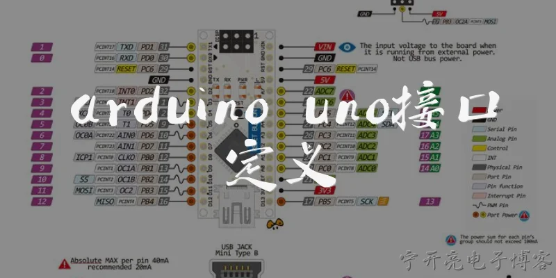
A: The Arduino Uno pinout is divided into several key sections: power pins (VIN, 3.3V, 5V, GND, and RESET), analog input pins (A0–A5), and digital pins (0–13). Digital pins 0 and 1 are also used for serial communication (RX/TX), so they should be avoided when using the serial monitor. Pins 3, 5, 6, 9, 10, and 11 support PWM output, marked with a tilde (~). Pins 10–13 are dedicated to SPI communication, while pins 13 also has an onboard LED. Additionally, pins A4 and A5 serve as SDA and SCL for I2C. There is also an ICSP header for direct programming and a USB port for power and data. Understanding these sections helps you connect sensors, actuators, and shields correctly without damaging the board.
Q: Which Arduino Uno pins provide PWM output and how do you use them?
A: On the Arduino Uno, six digital pins support PWM (Pulse Width Modulation): pins 3, 5, 6, 9, 10, and 11. These pins are marked with a tilde (~) symbol on the board. PWM allows you to simulate analog output by rapidly switching a digital pin on and off. You use the analogWrite() function, which takes a value between 0 (always off) and 255 (always on). For example, analogWrite(9, 128) gives a 50% duty cycle on pin 9. This is useful for dimming LEDs, controlling motor speed, or generating audio tones. Note that PWM frequency is about 490 Hz on most pins, except pins 5 and 6 which run at about 980 Hz. Keep in mind that PWM does not produce a true analog voltage; it’s a square wave. For true analog output, you’d need external circuitry like a low-pass filter.
Q: How do I connect I2C devices to the Arduino Uno using its pinout?
A: To connect I2C devices to the Arduino Uno, you use the dedicated SDA (Serial Data) and SCL (Serial Clock) pins. On the Uno, these are located on analog pins A4 (SDA) and A5 (SCL). The Uno also has a separate 4-pin I2C header near the USB port on some revisions (though not on all clones). For reliable communication, connect the device’s SDA to A4, SCL to A5, and ensure both devices share a common ground. I2C requires pull-up resistors on both lines, typically 4.7kΩ to 5V. Many breakout boards include these resistors, but if not, you must add them externally. The Wire library in Arduino IDE handles the protocol. Use Wire.begin() to initialize, then Wire.beginTransmission(), Wire.write(), and Wire.endTransmission() for sending data. This setup supports multiple devices on the same bus using unique addresses.
Q: What is the purpose of the ICSP header on the Arduino Uno pinout?
A: The ICSP (In-Circuit Serial Programming) header on the Arduino Uno is a 2x3 pin male connector located near the digital pins. It allows you to program the ATmega328P microcontroller directly, bypassing the USB interface. This is useful when the bootloader is corrupted, when you want to burn a new bootloader, or when using the Uno as an ISP programmer for another Arduino. The header provides access to MISO, MOSI, SCK, RESET, VCC, and GND. You connect an external programmer like USBtinyISP or another Arduino loaded with the ArduinoISP sketch. In the Arduino IDE, select the programmer and use “Burn Bootloader” or “Upload Using Programmer.” The ICSP header is essential for advanced users doing low-level firmware updates. Note that it is not the same as the 6-pin ICSP used on some other boards; the Uno uses a standard 6-pin layout.
Words of experience
Common scenarios of "Arduino Uno pinout"
【Teacher】 Good morning, class! Today we'll discuss the Arduino Uno pinout. Can anyone tell me what a pinout is?
【Student】 Isn't it like a map of all the pins on the board and what they do?
【Teacher】 Exactly! The pinout shows the function of each pin. Let's start with the power pins. Who can name some?
【Student】 There's 5V, 3.3V, and GND, right?
【Teacher】 Yes, and also Vin and the reset pin. Now, what about the digital pins?
【Student】 Digital pins are numbered 0 to 13. Some have special functions like PWM and serial communication.
【Teacher】 Correct. Pins 0 and 1 are used for RX and TX, so it's best to avoid them for general I/O if you're using serial. What about PWM pins?
【Student】 PWM pins are marked with a tilde (~). On the Uno, they are pins 3, 5, 6, 9, 10, and 11.
【Teacher】 Great! Now, let's move to the analog pins. How many analog pins does the Uno have?
【Student】 It has six analog input pins, labeled A0 to A5. They can also be used as digital pins.
【Teacher】 Yes, and they have a 10-bit resolution, so values from 0 to 1023. Now, what about the communication pins?
【Student】 There are dedicated pins for I2C (SDA and SCL) and SPI (MOSI, MISO, SCK, SS). On the Uno, SDA is A4 and SCL is A5.
【Teacher】 Exactly. And the SPI pins are on the ICSP header and also digital pins 11, 12, 13. Now, let's talk about the reset pin.
【Student】 The reset pin is used to reset the microcontroller. It's active low, so pulling it low resets the board.
【Teacher】 Correct. Also, there's a built-in LED on pin 13. Can you explain why that's useful?
【Student】 It's handy for testing without external components. You can blink it to verify your code is running.
【Teacher】 Right. Now, let's discuss the pin current limits. What is the maximum current per pin?
【Student】 I think it's 20 mA per pin, but not more than 40 mA absolute maximum. And the total current for all pins shouldn't exceed 200 mA.
【Teacher】 Good. Always use resistors with LEDs to limit current. Now, any questions about the pinout?
【Student】 No, I think I understand it now. Thanks!