PCB power supply toroidal:What is a toroidal transformer and why is it used in PCB power supplies?
Q: What is a toroidal transformer and why is it used in PCB power supplies?
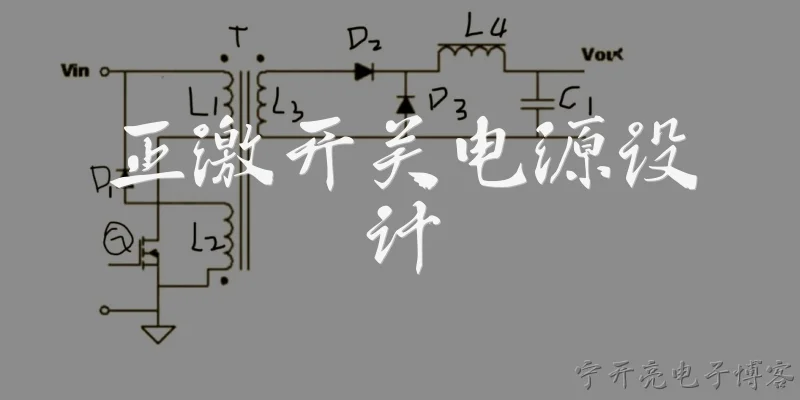
A: A toroidal transformer uses a donut-shaped magnetic core, typically made of ferrite or powdered iron, with windings wrapped around it. In PCB power supplies, it offers several advantages over traditional EI transformers: lower electromagnetic interference due to the closed magnetic path, higher efficiency, smaller size for the same power rating, and lower audible noise. Its compact shape also simplifies PCB layout. Toroidal transformers are commonly found in switch-mode power supplies and DC-DC converters, where they step up or step down voltages while minimizing core losses and stray magnetic fields that could affect nearby sensitive components.
Q: How do you select a toroidal transformer for a PCB power supply design?
A: Selecting a toroidal transformer for PCB power supply involves several key parameters: power rating, primary and secondary voltages, operating frequency, and core material. For switch-mode supplies, ferrite cores are standard due to low losses at high frequencies (20 kHz to 1 MHz). Calculate the required turns ratio based on input and output voltages, and choose a core size that handles the peak flux without saturation. Also consider window area for winding space, temperature rise, and isolation requirements. Manufacturers provide datasheets with inductance, saturation current, and DC resistance, which help optimize efficiency and thermal performance.
Q: What are the main causes of failure in toroidal transformers used in PCB power supplies?
A: Common failure modes in toroidal transformers for PCB power supplies include core saturation due to excessive current or volt-second imbalance, insulation breakdown from high voltage spikes or thermal aging, and mechanical stress from poor mounting or vibration. Overheating can degrade wire insulation, leading to shorted turns. In switch-mode designs, inadequate snubbing or leakage inductance can cause voltage ringing that exceeds winding insulation ratings. Also, core cracking from thermal cycling or physical impact reduces inductance and increases losses. Proper derating, good thermal management, and robust PCB mounting help prevent these failures and extend transformer life.
Q: How does a toroidal transformer reduce EMI in PCB power supplies?
A: A toroidal transformer reduces EMI because its closed-loop magnetic core confines the magnetic flux almost entirely within the core, unlike EI transformers with air gaps that radiate stray fields. This minimizes radiated emissions that could couple into nearby traces or components. Additionally, the symmetrical winding structure cancels most external magnetic fields, lowering common-mode noise. The low leakage inductance also reduces high-frequency ringing and associated conducted EMI. As a result, toroidal transformers help PCB power supplies meet stringent EMC standards, often requiring less filtering and shielding, which saves board space and cost.
Q: Can a toroidal transformer be used in both AC-DC and DC-DC PCB power supplies?
A: Yes, toroidal transformers are versatile and used in both AC-DC and DC-DC PCB power supplies, but with different design considerations. In AC-DC linear supplies, they operate at mains frequency (50/60 Hz) using laminated silicon steel cores for high inductance. In DC-DC switch-mode supplies, they operate at high frequencies using ferrite cores to reduce size and core loss. The key difference is core material and winding wire type—litz wire for high-frequency AC to reduce skin effect. Regardless of topology, the toroidal shape provides low EMI and high efficiency, making it suitable for a wide range of power conversion applications.
Dialogue about
Common scenarios of "PCB power supply toroidal"
【Electrical Engineer】 Hi, I'm designing a power supply for a sensitive analog circuit on a PCB. I'm considering using a toroidal transformer. What are the main advantages?
【Power Supply Designer】 Toroidal transformers have several key benefits: lower stray magnetic field, higher efficiency, smaller size for the same power rating, and lower audible noise. They're great for sensitive applications.
【Electrical Engineer】 That sounds ideal. But I've heard they can have higher inrush current. How do I handle that on a PCB?
【Power Supply Designer】 Yes, toroids can have high inrush due to low core saturation. You can use an NTC thermistor, a fixed resistor with a relay bypass, or an active inrush limiter circuit.
【Electrical Engineer】 Okay. What about PCB layout? Are there special considerations for mounting a toroidal transformer?
【Power Supply Designer】 Absolutely. Keep it away from sensitive analog traces. Use a star ground and place the transformer at the edge of the board. Also, ensure proper clearance for the mounting bolt and avoid running traces under it.
【Electrical Engineer】 Should I use a metal shield around the transformer to reduce EMI further?
【Power Supply Designer】 A shield can help, but toroids already have low EMI. If you use a shield, connect it to chassis ground, not signal ground. Also, avoid creating a shorted turn with the mounting hardware.
【Electrical Engineer】 What about the core material? I see options like silicon steel, ferrite, and nanocrystalline. Which is best for audio frequencies?
【Power Supply Designer】 For audio frequencies (20Hz-20kHz), silicon steel or permalloy is common. Ferrite is for higher frequencies. Nanocrystalline is excellent but expensive. Choose based on your budget and performance needs.
【Electrical Engineer】 I'm also concerned about thermal management. Toroids are compact, so heat dissipation might be an issue.
【Power Supply Designer】 Yes, toroids can run hot. Ensure adequate ventilation and consider derating. You can also use a thermal pad to the chassis or a heatsink if needed. Monitor temperature with a thermistor.
【Electrical Engineer】 How do I calculate the required VA rating for my application?
【Power Supply Designer】 Sum the power requirements of all secondary loads, then add margin for efficiency and regulation. Typically, add 20-30% headroom. Also, consider the power factor if you have non-linear loads.
【Electrical Engineer】 What about series or parallel connection of multiple secondaries? Any pitfalls?
【Power Supply Designer】 Yes, ensure phase matching. For parallel, use identical windings and balance currents with small series resistors. For series, watch insulation ratings. Always verify polarity before connecting.
【Electrical Engineer】 I've seen some toroids with a static shield between primary and secondary. Is that necessary for my application?
【Power Supply Designer】 A static shield reduces common-mode noise coupling. For sensitive analog circuits, it's highly recommended. It adds cost but improves performance significantly.
【Electrical Engineer】 Great. Finally, any recommendations for mounting hardware to avoid shorted turns?
【Power Supply Designer】 Use a non-conductive mounting bolt or insulating washers. Ensure the bolt doesn't form a complete loop around the core. Also, use a rubber pad to damp vibrations. That should cover it.