Microcontroller Crystal Oscillator Circuit:What is the role of a crystal oscillator circuit in a microcontroller?
Q: What is the role of a crystal oscillator circuit in a microcontroller?
A: A crystal oscillator circuit in a microcontroller provides a highly stable and accurate clock signal, which is essential for timing operations, instruction execution, and peripheral synchronization. According to the American National Standards Institute (ANSI) and IEEE Std 100, a crystal oscillator uses the mechanical resonance of a piezoelectric crystal to generate a precise frequency. This frequency serves as the master clock for the microcontroller's CPU, timers, and communication interfaces. Official microcontroller datasheets from manufacturers like Microchip and Texas Instruments emphasize that the crystal oscillator ensures reliable operation over temperature and voltage variations, making it critical for applications requiring precise timing, such as UART, SPI, and USB communications.
Q: How does a crystal oscillator differ from a ceramic resonator in microcontroller circuits?
A: A crystal oscillator offers higher frequency stability and accuracy compared to a ceramic resonator. According to the IEEE Standards Association, quartz crystals typically achieve tolerances of ±10 to ±100 ppm, while ceramic resonators have tolerances of ±0.5% to ±1%. This difference makes crystals preferable for applications demanding precise timing, such as real-time clocks or high-speed serial communication. Ceramic resonators are cheaper and more rugged but less accurate. Official application notes from Microchip (AN2648) and Texas Instruments (SNAA291) highlight that microcontroller designs should choose crystal oscillators when timing precision is critical, and ceramic resonators for cost-sensitive, less demanding applications.
Q: What are the key components of a typical microcontroller crystal oscillator circuit?
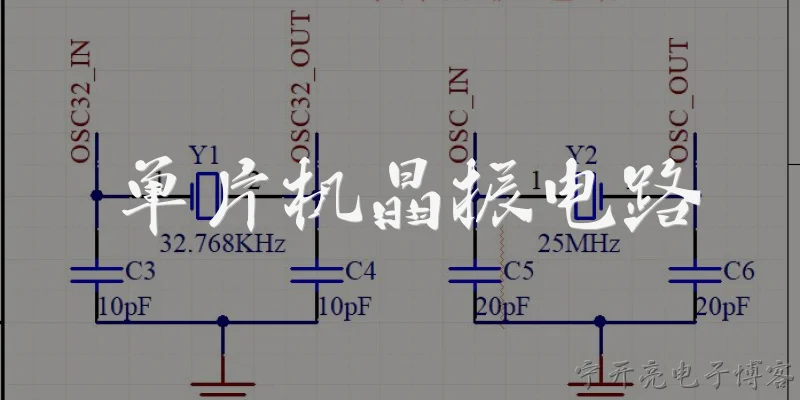
A: A typical microcontroller crystal oscillator circuit includes a quartz crystal, two load capacitors (C1 and C2), and sometimes a series resistor (Rs). According to the International Electrotechnical Commission (IEC) standard IEC 60122, the load capacitors are chosen to match the crystal's specified load capacitance, ensuring oscillation at the desired frequency. The series resistor may be used to limit drive power and prevent overdrive. Official microcontroller datasheets, such as those from STMicroelectronics (AN2867), specify that the crystal should be placed as close as possible to the microcontroller's oscillator pins to minimize parasitic capacitance and noise. Proper grounding and layout are also critical for reliable oscillation.
Q: How do you calculate the load capacitors for a microcontroller crystal oscillator?
A: To calculate load capacitors C1 and C2 for a crystal oscillator, use the formula: CL = (C1 * C2) / (C1 + C2) + Cstray, where CL is the crystal's specified load capacitance and Cstray is the stray capacitance (typically 2-5 pF). According to the IEEE Std 100 and application notes from Texas Instruments (SNAA291), if C1 = C2, then C1 = 2 * (CL - Cstray). For example, if CL = 12 pF and Cstray = 3 pF, then C1 = C2 = 18 pF. Official microcontroller datasheets recommend using NP0 or C0G capacitors for stability over temperature. Always verify with the crystal manufacturer's data sheet.
Q: What are common troubleshooting issues with microcontroller crystal oscillator circuits?
A: Common issues with microcontroller crystal oscillator circuits include no oscillation, unstable frequency, or startup failure. According to application notes from Microchip (AN2648) and STMicroelectronics (AN2867), causes may include incorrect load capacitors, excessive stray capacitance, poor PCB layout, or insufficient drive level. Official guidelines recommend checking the crystal's specifications, ensuring proper grounding, and using an oscilloscope with a low-capacitance probe to measure the oscillator pins. Another issue is the use of wrong crystal mode (fundamental vs. overtone). Additionally, temperature extremes can shift frequency. Troubleshooting steps include verifying component values, reducing trace lengths, and consulting the microcontroller's oscillator section in the datasheet.
Dialogue about
Common scenarios of "Microcontroller Crystal Oscillator Circuit"
【Engineer】 Hi, I'm working on a microcontroller project and need to design the crystal oscillator circuit. Can you help me understand the basics?
【Expert】 Sure! The crystal oscillator provides the clock signal for the microcontroller. It typically consists of a crystal, two load capacitors, and sometimes a series resistor. What microcontroller are you using?
【Engineer】 I'm using an STM32F103. The datasheet recommends an 8 MHz crystal with 20 pF load capacitors, but I'm not sure if that's optimal.
【Expert】 The load capacitors depend on the crystal's specified load capacitance (CL) and stray capacitance. The formula is C1 = C2 = 2*(CL - Cstray). If CL is 20 pF and stray is about 5 pF, then C1 = C2 = 30 pF. But the datasheet might give typical values for a specific crystal. Always check the crystal's datasheet.
【Engineer】 Ah, so the 20 pF in the STM32 datasheet might be the load capacitance of the crystal, not the capacitor values? I need to choose capacitors accordingly.
【Expert】 Exactly. The STM32 datasheet often specifies the recommended crystal CL, not the capacitor values. You need to select capacitors that match your crystal's CL. Also, consider the ESR (equivalent series resistance) and drive level.
【Engineer】 What about the series resistor? Some designs include a resistor in series with the crystal, but I'm not sure when it's needed.
【Expert】 The series resistor (Rs) is often used to limit the drive power to the crystal, preventing overdrive and reducing EMI. It's especially important if the crystal has a low ESR or if the oscillator circuit has high gain. Start with a small value like 100 ohms and adjust based on measurements.
【Engineer】 How do I measure the oscillator performance? I don't have a fancy oscilloscope with high bandwidth.
【Expert】 You can use a frequency counter or a microcontroller's internal clock output if available. Also, check the startup time and stability. If you have access to a spectrum analyzer, you can check for harmonics. But often, if it oscillates and the microcontroller runs reliably, it's good enough.
【Engineer】 I've heard about negative resistance and gm. How does that factor into the design?
【Expert】 The oscillator circuit must provide enough negative resistance to overcome the crystal's ESR and other losses. The transconductance (gm) of the inverter inside the microcontroller must be sufficient. Typically, the microcontroller's oscillator pins are designed to work with a wide range of crystals, but if you use a high-ESR crystal, it might not start. Check the microcontroller's datasheet for the recommended ESR range.
【Engineer】 What about PCB layout? Any tips?
【Expert】 Keep the crystal and capacitors as close to the microcontroller pins as possible. Use short traces, avoid vias, and keep the ground plane solid underneath. Also, guard the oscillator traces with ground to reduce noise coupling.
【Engineer】 Should I use a ground plane under the crystal? I've seen some designs with a cutout.
【Expert】 A solid ground plane is generally good, but some designers put a cutout under the crystal to reduce stray capacitance. However, that can also increase EMI. It's a trade-off. For most designs, a solid ground plane works fine. Just ensure no noisy signals run underneath.
【Engineer】 What about using an external oscillator instead? Like a can oscillator?
【Expert】 Yes, an external oscillator (e.g., a crystal oscillator module) can be more robust and easier to design, but it's more expensive and consumes more power. If you need high precision or have a difficult layout, it's a good option.
【Engineer】 Thanks! I think I have a better idea now. I'll start with the recommended values and adjust based on testing.
【Expert】 You're welcome! Remember to always refer to the crystal and microcontroller datasheets. Good luck with your design!