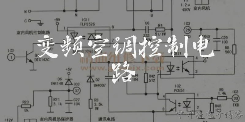
Basics of Electrical Circuit Diagrams:What are the basic components of an electrical circuit diagram?
Q: What are the basic components of an electrical circuit diagram?
A: An electrical circuit diagram, also known as a schematic, uses standardized symbols to represent the components and connections in a circuit. The basic components include power sources (like batteries or DC power supplies), conductors (wires that carry current), loads (such as resistors, lamps, or motors), and control devices (switches, relays, or transistors). Each component is drawn with a unique symbol: a battery is shown as parallel lines of alternating length, a resistor as a zigzag line, a lamp as a circle with a cross, and a switch as a break in a line with a hinged arm. These symbols are connected by straight lines representing wires, and junctions are marked with dots. Understanding these fundamentals is essential because the diagram shows how current flows from the source, through the circuit, and back to the source. Without knowing the symbols, you cannot interpret or design circuits. The diagram also indicates values (e.g., 10Ω, 5V) and reference designators (R1, C2) to identify each part. Mastering these basics allows you to read, troubleshoot, and create your own circuit diagrams.
Q: How do you read and interpret an electrical circuit diagram?
A: Reading an electrical circuit diagram involves following the path of current from the power source through various components. Start by identifying the power source, typically at the top or left, and the ground or return path at the bottom or right. Then trace the wires: lines represent electrical connections, and dots indicate where wires join. Look for series and parallel arrangements. In a series circuit, components are connected end-to-end, so the same current flows through all of them. In a parallel circuit, components are connected across the same voltage, so the current splits. Next, identify the function of each symbol: resistors limit current, capacitors store charge, diodes allow one-way flow, and switches control the path. Pay attention to labels and values, such as 'R1 100Ω' or 'C1 10µF.' Also, note any test points or voltage markers. To interpret, apply Ohm's law and Kirchhoff's laws to calculate unknown voltages and currents. For example, if you see a 9V battery in series with two resistors, you can find the current by dividing voltage by total resistance. Practice with simple diagrams first, then move to complex ones with integrated circuits. This skill is crucial for troubleshooting and design.
Q: Why are electrical circuit diagrams important in engineering and troubleshooting?
A: Electrical circuit diagrams are indispensable in engineering and troubleshooting because they provide a universal language for representing complex electrical systems. In engineering, they are used to design, simulate, and document circuits before physical construction. A schematic allows engineers to verify connections, calculate parameters, and ensure safety without building a prototype. During manufacturing, diagrams guide assembly and wiring. In troubleshooting, they are the primary tool for diagnosing faults. By comparing actual measurements with expected values from the diagram, a technician can locate opens, shorts, or faulty components. For example, if a lamp doesn't light, you can trace the circuit from the power source to the lamp, checking for voltage at each point. The diagram also helps in understanding the logic of control systems, such as relay logic or microcontroller I/O. Moreover, standardized symbols (per IEC or ANSI) ensure that a diagram created in one country can be read anywhere. Without circuit diagrams, repairing modern electronics—from smartphones to industrial machines—would be nearly impossible. They save time, reduce errors, and enhance safety by clearly showing how components interact.
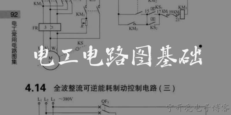
Dialogue about
Common scenarios of "Basics of Electrical Circuit Diagrams"
【Teacher】 Good morning, class! Today we'll learn about the basics of electrical circuit diagrams. Can anyone tell me what a circuit diagram is?
【Student】 A circuit diagram is a drawing that uses symbols to represent electrical components and their connections.
【Teacher】 Exactly! It's a simplified way to show how components are connected. What are some common components you might see?
【Student】 Batteries, resistors, capacitors, switches, and wires.
【Teacher】 Good. Each has a standard symbol. For example, a battery is represented by parallel lines of different lengths. Can you describe the symbol for a resistor?
【Student】 It's a zigzag line, like a series of peaks and valleys.
【Teacher】 Correct. Now, what is the purpose of a circuit diagram?
【Student】 To show how components are connected and to help in analyzing and building the circuit.
【Teacher】 Yes, it's a universal language for engineers. Let's talk about series and parallel circuits. What's the difference?
【Student】 In a series circuit, components are connected end-to-end, so the same current flows through all. In parallel, components are connected across each other, so they share the same voltage.
【Teacher】 Excellent. Can you give an example of a series circuit?
【Student】 A string of old Christmas lights where if one bulb burns out, the whole string goes out.
【Teacher】 Right. And parallel?
【Student】 The electrical outlets in a house are in parallel, so each device gets the full voltage and can operate independently.
【Teacher】 Perfect. Now, what is Ohm's Law and how does it relate to circuit diagrams?
【Student】 Ohm's Law states that V = I * R, where V is voltage, I is current, and R is resistance. It helps calculate unknown values in a circuit diagram.
【Teacher】 Yes. Let's say you have a 9V battery and a 3 ohm resistor. What's the current?
【Student】 I = V / R = 9V / 3Ω = 3A.
【Teacher】 Great! In circuit diagrams, we also use ground symbols. What does a ground symbol represent?
【Student】 It represents a common reference point for voltage measurements, often connected to the earth or a common return path.